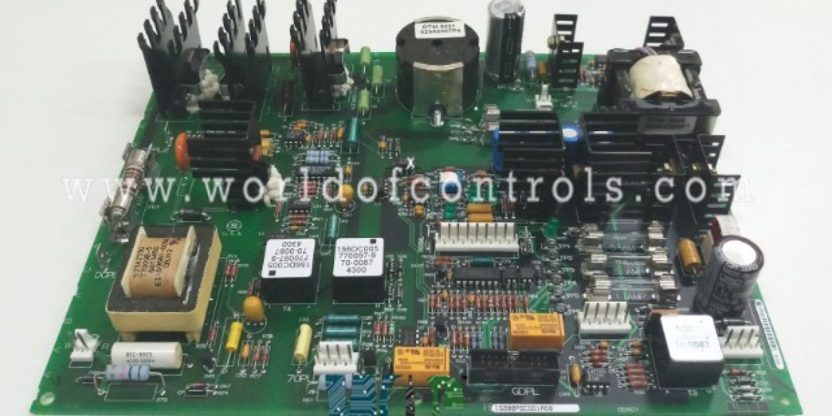

In GE’s Mark VI turbine control environment, reliable low‑voltage power and precise contactor control are just as critical as high‑level control logic. Without a stable internal power backbone and coordinated contactor actuation, even the most advanced controller cannot keep a gas or steam turbine online. The IS200PSCDG1A Power Supply/Contactor Driver Board sits at the heart of this infrastructure. It converts high‑energy DC link power into regulated control supplies, manages contactor coils, and provides the permissive path that lets the exciter and drive hardware start, run, and shut down safely.
The IS200PSCDG1A is designed as a combined power supply and contactor driver board for EX2000 PWM‑based excitation within the Mark VI Speedtronic family. It typically draws its input from the exciter DC link and converts this into multiple isolated low‑voltage rails for use by various control and gate‑drive boards. At the same time, it incorporates a dedicated contactor supply and coil‑drive circuitry to operate key relays associated with starting and stopping the PWM regulator and related power devices. By combining these functions on a single printed circuit assembly, GE reduces wiring complexity and ensures that the logic controlling contactors is tightly coupled with the health of the power supplies feeding the control system.
Power distribution begins on the IS200PSCDG1A with its DC link input. The board accepts a relatively wide DC voltage window, typically from around 80 Vdc up to several hundred volts during normal operation, and is designed to tolerate short‑term excursions associated with dynamic discharge or transient events. From this single high‑voltage source, the board generates the low‑voltage rails needed by the Mark VI exciter and associated modules. Commonly, you will see outputs such as ±24 V, ±15 V, and +5 V distributed to control boards, I/O modules, and communication interfaces. This multi‑rail architecture allows analog circuits, digital logic, and interface electronics to operate at their optimal voltage levels while being galvanically isolated from the high‑energy DC bus.
One of the important roles of the IS200PSCDG1A is to support gate‑drive and communication hardware. For example, it often generates an isolated AC‑like square‑wave (in the tens of volts range) that is passed through high‑frequency transformers to remote gate driver boards and LAN terminal boards. These secondary modules then rectify and regulate that signal locally to produce their own isolated low‑voltage supplies. This approach reduces noise coupling, improves isolation between power stages and logic, and simplifies the distribution of auxiliary power within the exciter cabinet.
Beyond the main control supplies, the board also includes auxiliary converters to feed special loads. A typical example is an isolated 70 Vdc output, sized to support multiple digital inputs or relay coils on external boards. This 70 Vdc rail is especially important for safety‑critical circuits such as emergency stop chains and permissive relays. By keeping this supply isolated and monitored, the IS200PSCDG1A ensures that a fault on a field wiring circuit does not drag down core control power, and that loss of this auxiliary supply can be quickly detected and acted upon.
On the contactor side, the IS200PSCDG1A incorporates a dedicated power path and driver stage for key contactors such as main DC link contactors or exciter enable contactors. Typically, the board will take DC link power, step it down through a buck converter to a level appropriate for the contactor coil (often around 100 Vdc for certain designs), and then route this through transistorized drivers controlled by optically isolated logic signals. The use of optocouplers helps maintain a clear isolation boundary between low‑voltage control logic and high‑voltage coil circuits, improving noise immunity and safety.
In Mark VI applications, the contactors controlled by the IS200PSCDG1A usually fulfill two key roles: providing the “run” path for the PWM exciter and enforcing a fast, reliable stop when conditions demand it. One relay is typically energized when the control system issues a run command and all permissives are satisfied. This relay closes the power path or enables the main contactor, allowing the exciter and drive hardware to energize the generator field or motor. Another relay is connected into an emergency stop chain; if this relay drops out—due to an E‑stop pushbutton, protective trip, or loss of required supply—the power path is immediately interrupted and the PWM regulator is disabled.
From a control standpoint, the IS200PSCDG1A becomes the physical enforcement mechanism for logical decisions taken by the Mark VI controller. When the control module determines that conditions are safe to start, it sends an enable signal through communication and I/O paths that ultimately energizes a contactor driver on the PSCD board. When a stop or trip is necessary, the same chain is broken, causing the coil to de‑energize and opening the power path. Because the board is responsible for both generating the coil supply and switching it, any loss of its internal supply rails or detection of a serious fault can automatically remove the run permissive, adding an extra layer of fail‑safe behavior.
Reliability is further enhanced by the board’s component‑level design. You will typically find multiple fuses protecting different supply branches, metal‑oxide varistors for surge suppression, and robust electrolytic capacitors and inductors for filtering and energy storage. Heat sinks on key power devices help the board withstand the thermal stress of continuous operation in turbine environments, where ambient temperatures and cabinet heating can be significant. These hardware features ensure that the IS200PSCDG1A can deliver stable power and consistent contactor performance over many years of service.
For plant engineers and technicians, understanding how the IS200PSCDG1A manages both power distribution and contactor control is invaluable for troubleshooting. If multiple control boards report undervoltage or lose communication simultaneously, the root cause may be upstream on this power supply/contactor driver board. Likewise, if the exciter refuses to start despite all software permissives being met, checking whether the contactor coil voltage is present and being driven from the PSCD is a logical early step. Measuring DC link input, verifying low‑voltage rails, and confirming coil drive signals all help narrow down faults quickly.
In practical terms, the IS200PSCDG1A - Power Supply/Contactor Driver Board is the bridge between the high‑energy DC link and the sensitive Mark VI control electronics, and the gatekeeper for contactors that connect that energy to the exciter and drive hardware. By integrating robust power conversion, isolated auxiliary supplies, and intelligent contactor control, it plays a central role in keeping Mark VI‑based turbine systems reliable, safe, and responsive to operator commands and protective logic alike.
Check Also - IS200ERDDH1A - DYNAMICS DISCHARGE GE BOARD